Home < Dental Professional < KIT & Tools < Surgical Tools



| |
ø2.0 |
ø3.0 |
ø3.3 |
ø3.6 |
| 7 |
TDE2007LC |
3D3007LC01 |
- |
- |
| 8.5 |
TDE2008LC |
3D3008LC01 |
- |
- |
| 10 |
TDE2010LC |
3D3010LC01 |
- |
- |
| 11.5 |
TDE2011LC |
3D3011LC01 |
3D3311LC01 |
3D3611LC01 |
| 13 |
TDE2013LC |
3D3013LC01 |
- |
- |
| |
ø3.8 |
ø4.1 |
ø4.3 |
ø4.6 |
| 7 |
3D3807LC01 |
- |
- |
- |
| 8.5 |
3D3808LC01 |
- |
- |
- |
| 10 |
3D3810LC01 |
- |
- |
- |
| 11.5 |
3D3811LC01 |
3D4111LC01 |
3D4311LC01 |
3D4611LC01 |
| 13 |
3D3813LC01 |
- |
- |
- |
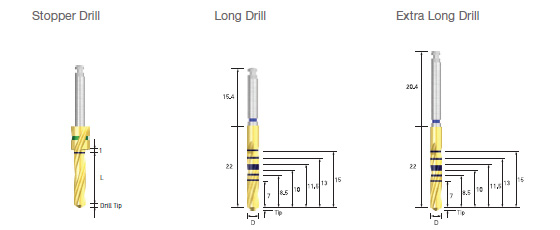
- ㆍPackage unit : each part
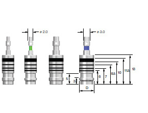
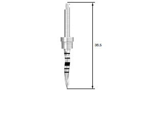
- ㆍLong stopper (6 mm) : Posterior surgery may be performed even without drill extension
- ㆍThe color coding on the stopper indicates the drill length
- ㆍThe tip length of a 2.0 twist drill is 0.6 mm, and the other tip length of drills, 0.8mm~1mm

| |
ø2.0 |
ø2.7 |
ø3.0 |
ø3.15 |
ø3.3 |
| 13 |
TDE2013FNLC |
|
3D3013FNLC |
|
|
| 16 |
TDE2015FNLC |
3D2715FNLC01 |
3D3015FNLC01 |
3D3115FNLC01 |
3D3315FNLC01 |
| |
ø3.6 |
ø3.8 |
ø4.1 |
ø4.3 |
ø4.6 |
| 13 |
|
3D3813FNLC |
|
|
3D4613FNLC |
| 16 |
3D3615FNLC01 |
3D3815FNLC01 |
3D4115FNLC01 |
3D4315FNLC01 |
3D4615FNLC01 |
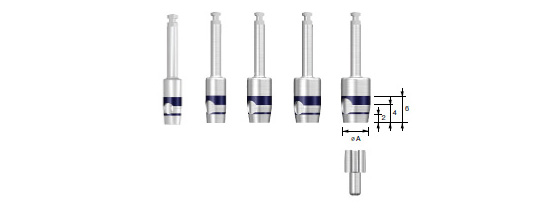
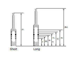
- ㆍPackage unit : each part
- ㆍCuts the stopper of a 15 mm drill to facilitate depth adjustment in the ridge
- ㆍThe laser marking indicates the length, thereby enabling all drilling lengths (7-15 mm) using one drill
- ㆍHandles are color-coded to indicate drill length

| |
ø2.0 |
ø2.7 |
ø3.0 |
ø3.15 |
ø3.3 |
| |
TDE2015FNEC |
3D2715FNEC |
3D3015FNEC |
3D3115FNEC |
3D3315FNEC |
| |
ø3.6 |
ø3.8 |
ø4.1 |
ø4.3 |
ø4.6 |
| |
3D3615FNEC |
3D3815FNEC |
3D4115FNEC |
3D4315FNEC |
3D4615FNEC |
- ㆍPackage unit : each part
- ㆍFor sufficient intermaxillary gap as in the anterior part, drilling may be performed even without drill extension
- ㆍThe laser marking indicates the length, thereby enabling all drilling lengths (7-15 mm) using one drill
- ㆍHandles are color-coded to indicate drill length
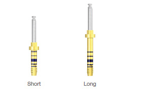
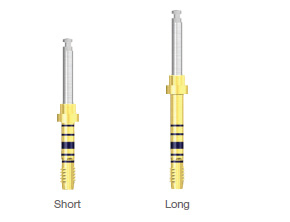
| ①/ ②/ ③ |
ø2.2/3.0 |
ø3.0/3.6 |
ø3.0/3.6/4.1 |
ø3.0/4.1/4.6 |
| Short |
2D2230S |
2D3036S |
2D3041S |
2D3046S |
| Long |
2D2230L |
2D3036L |
2D3041L |
2D3046L |
| Coloring |
Yellow |
Green |
Blue |
Red |
| Y-Dim. |
0.7mm |
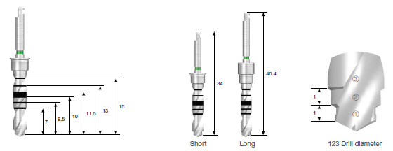
- ㆍPackage unit : each part
- ㆍThe color of 123drill handle part means the diameter and kind of main mixture to be used
- Yellow: F3.5, Green: F4.0, Blue: F4.5, Red: F5.0
- ㆍInstall the drill stop in order to adjust the drilling depth to intended level
- ㆍ123 twist drill has good cutting force and control of drilling depth may be difficult; therefore, it is highly recommended to use the drill stop
| |
ODS06 |
ODS07 |
ODS08 |
ODS09 |
ODS11 |
ODS12 |
ODS14 |
ODS16 |
| L(mm) |
6.2 |
7 |
8 |
9.5 |
11 |
12.5 |
14 |
15 |
| Coloring |
Purple |
White |
Yellow |
Red |
Blue |
Green |
Black |
Purple |
- ㆍPackage unit : each part
- ㆍThe length of drill stop means the remained actual length when the drill stop is installed on 123 twist drill
- ㆍThe lengths are differentiated with colors for convenient identification of lengths and return to KIT
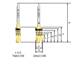
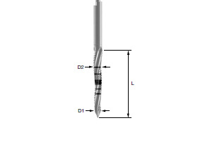
| Name |
D1 |
D2 |
Code |
| ø4.6 Twist Drills |
ø4.6 |
- |
3D4613FNLC |
| ø5.2 Direct Drill |
ø4.6 |
ø5.2 |
3D5213FNLC |
| ø5.5 Direct Drill |
ø4.6 |
ø5.5 |
3D5513FNLC |
| ø6.2 Direct Drill |
ø5.5 |
ø6.2 |
3D6213FNLC |
| ø6.5 Direct Drill |
ø5.5 |
ø6.5 |
3D6513FNLC |
- ㆍDirect drill: 2-stepped drill equipped with both pilot and twist drill function
1. Enables final drilling without pilot drilling
2. Enhancement of initial fixation in the extract socket by decreasing
the dead space at the apex area
| |
ø3.5 |
ø4.0 |
ø4.5 |
ø5.0 |
| 7 |
TPD3C3507 |
TPD3C4007 |
TPD3C4507 |
TPD3C5007 |
| 8.5 |
TPD3C3508 |
TPD3C4008 |
TPD3C4508 |
TPD3C5008 |
| 10 |
TPD3C3510 |
TPD3C4010 |
TPD3C4510 |
TPD3C5010 |
| 11.5 |
TPD3C3511 |
TPD3C4011 |
TPD3C4511 |
TPD3C5011 |
| 13 |
TPD3C3513 |
TPD3C4013 |
TPD3C4513 |
TPD3C5013 |
| 15 |
TPD3C3515 |
TPD3C4015 |
TPD3C4515 |
TPD3C5015 |
| Length of Drill Tip |
0.8mm |
0.9mm |
1.0mm |
1.0mm |
- ㆍPacking Unit : each part
1. Enables final drilling without pilot drilling
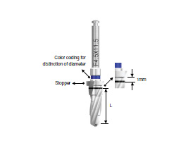
- ㆍProcessing exclusive use Taper Drill for III fixture diameter and length
- ㆍStopper drill with 1mm margin
- ㆍColor coding on the shank indicates the fixture diameter
(ø3.5:Yellow, ø4.0:Green, ø4.5:Blue, ø5.0:Red )
| |
∅6.0 |
∅7.0 |
| 6 |
TPD3C6006 |
TPD3C7006 |
| 7 |
TPD3C6007 |
TPD3C7007 |
| 8.5 |
TPD3C6008 |
TPD3C7008 |
| 10 |
TPD3C6010 |
TPD3C7010 |
| 11.5 |
TPD3C6011 |
TPD3C7011 |
| 13 |
TPD3C6013 |
TPD3C7013 |
- ㆍPacking Unit : each part
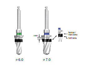
- ㆍProcessing exclusive use Taper Drill for Taper Ultra-Wide fixture diameter and
length
- ㆍStopper drill with 1mm margin
- ㆍColor coding on the shank indicates the fixture diameter
(ø6.0 : Green, ø7.0 : Blue)
| Type |
Code |
| Lance Drill |
Short |
AGDSC |
| Long |
AGDLC |
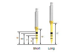
- ㆍPacking Unit : each part
- ㆍForms holes in the bone to facilitate initial drilling
- ㆍBone density can be determined through drilling
- ㆍTiN coating improves anti-corrosion and wear resistance
- ㆍPacking Unit : each part
- ㆍUsed as the initial drill
- ㆍInstall the drill stop in order to adjust the drilling depth to intended level
| |
D1 |
D2 |
L |
| OSLMDS |
1.5 |
2.0 |
13.0 |
| OSLMDL |
1.5 |
2.0 |
20.0 |
| OSLMD20S |
2.0 |
2.5 |
13.0 |
| OSLMD20L |
2.0 |
2.5 |
20.0 |
- ㆍPacking Unit : each part
- ㆍEnables the bodily change of drilling direction
- ㆍUsed to cut the ridge of the extracted socket
- ㆍFacilitates site preparation in the extracted socket
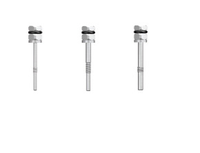
- ㆍPacking Unit : each part
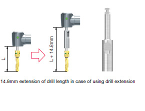
- ㆍExtends the length a drill and other hand tools
- ㆍUse by connecting the flat side of the drill handle to the flat side of the drill extension
- ㆍThe use of too much force is prohibited
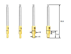
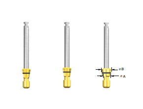
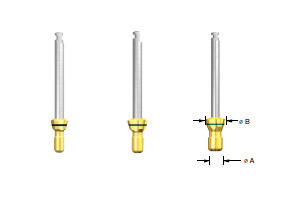
| øA |
øB |
Mini |
Regular |
Wide |
| 2.0 |
2.7 |
APD270C |
- |
- |
| 2.0 |
3.0 |
- |
APD300C |
- |
| 3.0 |
3.8 |
- |
- |
APD380C |
| 3.0 |
4.1 |
- |
- |
APD410C |
- ㆍPacking Unit : each part
- ㆍUsed for the path adjustment of a drilling hole
- ㆍWhen using the next size drill, the guide hole enables precise cutting
- ㆍTiN coating improves anti-corrosion and wear resistance
| |
F3.5 |
F4.0 |
F4.5 |
F5.0 |
| II type |
2CD35 |
2CD40 |
2CD45 |
2CD50 |
| III type |
3CD35 |
3CD40 |
3CD45 |
3CD50 |
| Coloring |
Yellow |
Green |
Blue |
Red |
- ㆍPacking Unit : each part
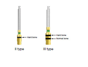
- ㆍIt is recommended to drill up to the lower end of the marking line
- ㆍThe marking line of II type cortical drill is based on hard bone
- ㆍThe lower end marking line of III type cortical drill is based on normal bone and
the upper end marking line is based on hard bone
- ㆍThe color of handle part means the diameter and kind of main mixture to
be used
- ㆍThe color of handle part means the diameter and kind of main mixture to
be used
- Yellow: F3.5, Green: F4.0, Blue: F4.5, Red: F5.0
| Spec. |
ø3.5 |
ø4.0 |
ø4.5 |
ø5.0 |
| Code |
CD2C35 |
CD2C40 |
CD2C45 |
CD2C50 |
- ㆍPacking Unit : each part
- ㆍUse after formation of final drill hole in case of hard bone(D1)
- ㆍThe marking line of II type cortical drill is based on hard bone
- ㆍExclusive drills are available to meet the fixture diameters
- ㆍIt is recommend that drilling performs up to under marking line
| Spec. |
ø3.5 |
ø4.0 |
ø4.5 |
ø5.0 |
| Code |
CD2C35 |
CD2C40 |
CD2C45 |
CD2C50 |
- ㆍPacking Unit : each part
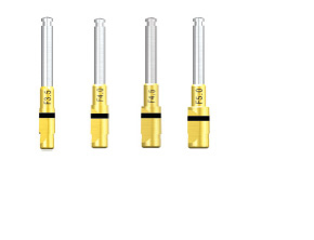
- ㆍDrills for expansion of cortical bone after use of straight drill
- ㆍUse after formation of final drill hole in case of more than normal bone
- ㆍExclusive drills are available to meet the fixture diameters
- ㆍThe lowest marking line is normal bone and the highest marking line is hard bone
- ㆍIt is recommend that drilling performs up to marking line
| Spec. |
ø3.5 |
ø4.0 |
ø4.5 |
ø5.0 |
| Code |
TCD4C35 |
TCD4C40 |
TCD4C45 |
TCD4C50 |
- ㆍPacking Unit : each part
- ㆍDrills for expansion of cortical bone after use of taper drill
- ㆍUse after formation of final drill hole in case of more than hard bone
- ㆍExclusive drills are available to meet the fixture diameters
- ㆍLower end marking line is based on 8.5mm or smaller fixture implant
Upper end marking line is based on 10mm or larger fixture implant
- ㆍIt is recommend that drilling performs up to the bottom marking line
| Name |
Code |
| F6.0 Cortical Dril |
CD4C60 |
| F7.0 Cortical Dril |
CD4C70 |
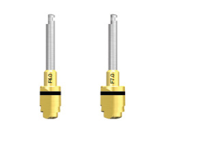
- ㆍUse after formation of final drill hole in case of hard bone(D1)
- ㆍExclusive drills are available to meet the fixture diameters
- ㆍIt is recommend that drilling performs up to the bottom marking line
| øA |
øB |
Regularø4.1 |
Regularø4.8 |
Wideø4.8 |
| 3.5 |
4.8 |
ASCD350C |
- |
- |
| 4.2 |
4.8 |
- |
ASCD420C |
- |
| 4.2 |
6.0 |
- |
- |
ASCDW420C |
- ㆍPacking Unit : each part
- ㆍForm fixture platform
- ㆍCut up to the bottom of the laser marking
- ㆍUse US Mini Countersink for SS Mini as needed
| øA |
øB |
Mini |
Regular |
Wide |
| 2.6 |
2.9 |
ACD330C |
- |
- |
| 3.5 |
4.1 |
- |
ACD375C |
- |
| 4.2 |
5.1 |
- |
- |
ACD500C |
- ㆍPacking Unit : each part
- ㆍForm space of fixture flange
- ㆍCut up to the bottom of the laser marking
- ㆍPacking Unit : each part
- ㆍInstruments for Wide PS, Wide of USIII, USII SA, USIII SA
- ㆍRecommendation drilling rpm : 300rp
| Platform |
ø4.8 |
ø4.8 |
ø6.0 |
|
ø4.1 |
ø4.8 |
| Short |
OSST41SC |
OSST48SC |
| Long |
OSST41LC |
OSST48LC |
- ㆍPacking Unit : each part
- ㆍUse for dense bone and form screw thread-shaped fixtures
- ㆍUse a torque wrench after connecting to the engine or mount extension
- ㆍTiN coating improves anti-corrosion and wear resistance
|
3.3 |
3.75 |
4.0 |
5.0 |
| Short |
4.8 |
OUST37SC |
OUST40SC |
OUST50SC |
| Long |
OUST33LC |
OUST37LC |
OUST40LC |
- |
- ㆍPacking Unit : each part
- ㆍUse for dense bone and form screw thread-shaped fixtures
- ㆍUse as a torque after connecting to the engine or a simple mount extension
- ㆍTiN coating improves anti-corrosion and wear resistance
| Diameter(ø) |
Code |
| ø4.0 |
APP400 |
| ø5.0 |
APP500 |
| ø6.0 |
APP600 |
| Full Set |
APPS |
- ㆍPacking Unit : Individual and general set packing
- ㆍUse for checking the direction and location for bone preparation
- ㆍPredicts the diameter of an abutment to be secured
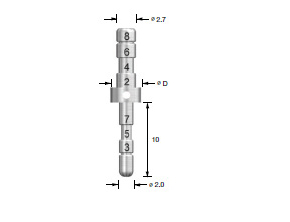
| D |
ø4.0 |
ø5.0 |
| Code |
OPP400 |
OPP500 |
- ㆍPacking Unit : each part
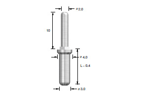
- ㆍParallel Pin 123 Twist Drill only
- ㆍUse for checking the direction and location for bone preparation
- ㆍUse the lower part for initial drilling and higher part for F3.5 (ø2.2/3.0) drilling
- ㆍPacking Unit : each part
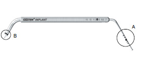
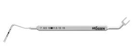
- ㆍA : Measurement of drilling length (7-15 mm)
- ㆍB : Measurement of gingival height following external fixture grafting
- ㆍPacking Unit : each part
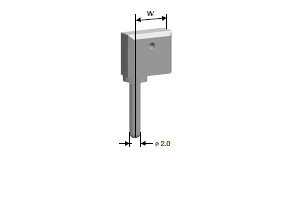
- ㆍUse as drilling depth measurement and open wrench
- ㆍUse for separating Mount in case of soft bone
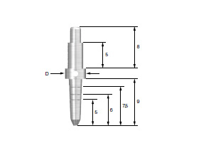
| Diameter(D) |
ø5.2 |
ø5.0 |
ø6.2 |
ø6.5 |
| Code |
UWFTP52 |
UWFTP55 |
UWFTP62 |
UWFTP65 |
- ㆍPacking Unit : each part
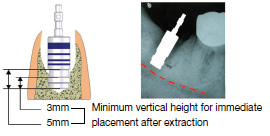
- ㆍCheck internal width and depth after extraction of a tooth
- ㆍCheck the drilling depth after using direct drill as final drill
- ㆍVerify the internal diameter of the failed implant socket
- ㆍThe purpose of Parallel Pin
| Diameter(ø) |
ø4.0 |
ø5.0 |
| Code |
ASDG360 |
ASDG430 |
- ㆍPacking Unit : each part
- ㆍMeasure the depth after the final drilling
| Length(mm) |
Code |
| 7 |
ADP607 |
| 8.5 |
ADP608 |
| 10 |
ADP610 |
- ㆍPacking Unit : Individual and general set packing
- ㆍIt is enable to check the drilling depth easily due to convenient design of top part
| Width(mm) |
Code |
| 2.5 |
APG201 |
| 6 |
APG202 |
| 11 |
APG203 |
- ㆍPacking Unit : Individual and general set packing
- ㆍIndicates the distance between fixtures
- ㆍUse after the first drilling (2.0)
- ㆍPacking Unit: each part
- ㆍMeasurement gingival height for selecting optimal abutment
- ㆍNon gloss treatment for improving identification
- ㆍPacking Unit: each part
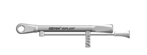
- ㆍPossibility of loading 10, 20, 30 and infinite Ncm
- ㆍUsed to adjust the installation location of implants or to tighten abutments or screws
- ㆍThe last line is approx. 40 Ncm
- ㆍTorque is applied to the center of the bar, which will be generated by pulling the bar
- ㆍThe product should be cleaned after use, and then sterilized for storage
- ㆍPacking Unit: each part
- ㆍPossibility of loading 10, 20, 30 and infinite Ncm
- ㆍOnly surgical unlimited wrench (If excessive torque is applied, the inside of bone or fixture may be damaged.)
- ㆍRotating direction is marked by an arrow for convenient identification
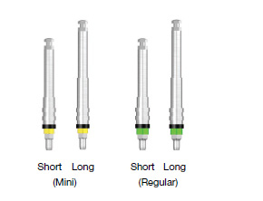
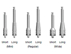
| Type |
Mini |
Regular |
| Short |
GSNMD32S |
GSNMD35S |
| Long |
GSNMD32L |
GSNMD35L |
- ㆍPacking Unit: each part
- ㆍTo enable the simultaneous measurement of gingival height upon treatment, grooves and laser markings are indicated at 1-mm (1-6 mm) intervals
- ㆍStopper designed for the prevention of fracture of the holding part and occurrence of foreign matter such as blood stain during the surgery
| Type |
Regular |
Wide |
| Short |
SSNOMD39RS |
| Long |
SSNOMD39RL |
- ㆍPacking Unit: each part
- ㆍSince the shape is similar to that of the internal fixture driver, even a high torque does not change the inside of the fixture
- ㆍStopper designed for the prevention of fracture of the holding part and occurrence of foreign matter such as blood stain during surgery
|
Mini |
Regular |
Wide |
| Short |
USNMD35MS |
USNMD41RS |
USNMD51WS |
| Long |
USNMD35ML |
USNMD41RL |
USNMD51WL |
- ㆍPacking Unit: each part
- ㆍTo enable the simultaneous measurement of gingival height upon treatment, grooves and laser markings are indicated at 1-mm (1-5 mm) intervals
- ㆍStopper designed for the prevention of fracture of the holding part and occurrence of foreign matter such as blood stain during the surgery
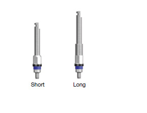
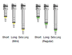
| Type |
Mini |
Regular |
| Short |
GSNMT32S |
GSNMT35S |
| Long |
GSNMT32L |
GSNMT35L |
| Extra Long |
GSNMT32E |
GSNMT35E |
- ㆍPacking Unit: each part
- ㆍTo enable the simultaneous measurement of gingival height upon treatment, grooves and laser markings are indicated at 1mm intervals
- ㆍStopper designed for the prevention of fracture of the holding part and occurrence of foreign matter such as blood stain during surgery
- ㆍThe fracture strength : 260Ncm
- ㆍIf excessive implant torque is applied, fracture may be resulted in; if unnecessary
large implant torque is expected, use a fixture driver. Also, imperfect installation
may result in fracture at the strength under fracture strength; therefore, perfect
installation should be checked before use
- ㆍSpecial attention should be paid; after occurrence of a fracture, restoration is impossible
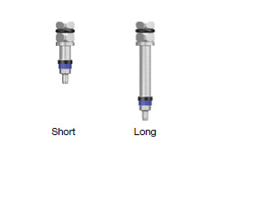
| Type |
Regular |
Wide |
| Short |
SSNOMD39RS |
| Long |
SSNOMD39RL |
- ㆍPacking Unit: each part
- ㆍSince the shape is similar to that of the internal fixture driver, even a high torque does not change the inside of the fixture
- ㆍStopper designed for the prevention of fracture of the holding part and occurrence of foreign matter such as blood stain during surgery
- ㆍThe fracture strength : 260Ncm
- ㆍIf excessive implant torque is applied, fracture may be resulted in; if unnecessary
large implant torque is expected, use a fixture driver. Also, imperfect installation
may result in fracture at the strength under fracture strength; therefore, perfect
installation should be checked before use.
- ㆍSpecial attention should be paid; after occurrence of a fracture, restoration is impossible.
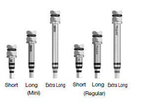
| Type |
Mini |
Regular |
| Short |
GSMFDS |
GSRFDS |
| Long |
GSMFDL |
GSRFDL |
| Extra Long |
GSMFDE |
GSRFDE |
- ㆍPacking Unit: each part
- ㆍFixture connection
- ㆍUse to place or remove a fixture after the separation of the mount
| Plaftorm(ø) |
Regular |
Wide |
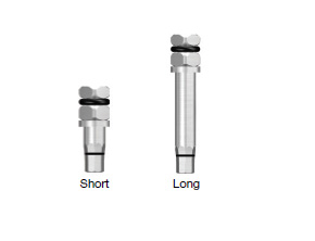
| Short |
SSRFDS |
| Long |
SSRFDL |
- ㆍPacking Unit: each part
- ㆍThe laser marking is designed for checking during the connection of a fixture
- ㆍUse for removal following fixture grafting and mount separation
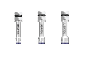
| Plaftorm(ø) |
Mini |
Regular |
Wide |
| Code |
USMFDL |
USRFDL |
USWFDL |
- ㆍPacking Unit: each part
- ㆍThe laser marking is designed for easy identification during the connection of fixtures
- ㆍUse for removal following fixture grafting and mount separation
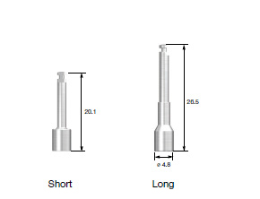
| Length |
Code |
| Short |
ASMDS |
| Long |
ASMDL |
- ㆍPacking Unit : each part
- ㆍUse for fixture grafting by connecting to a simple mount
- ㆍCompact design, internal holding function
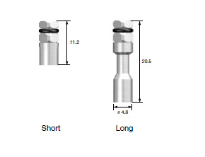
| Length |
Code |
| Short |
ASMES |
| Long |
ASMEL |
- ㆍPacking Unit : each part
- ㆍUse for extension of simple mount length, and use in case of inputting hand-torque by connecting with ratchet wrench.
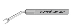
- ㆍPacking Unit: each part
- ㆍFor weak bone, use to separate the simple mount
- ㆍ30" neck angle enhances convenience of insertion in the oral cavity
| Code |
Application |
| ERFM |
US Mini, TS Mini |
| HRFR |
US Regular, SS Regular/Wide, TS Regular |
| ERFW |
US Wide |
- ㆍPacking Unit : each part
- ㆍWhen a fixture and the fixture mount are stuck, use after removing the fixture mount screw
- ㆍUse after the connection to a driver handle and a torque wrench
- ㆍInsert vertically and rotate clockwise
Tissue
Punch |
A |
ø3.3 |
ø3.8 |
ø4.3 |
ø4.8 |
ø5.3 |
| Code |
OSTP33 |
OSTP38 |
OSTP43 |
OSTP48 |
OSTP53 |
| Application Healing Abutment Standard |
TS |
ø4.0/ø4.5 |
ø4.5/ø5.0 |
ø5.0 |
ø6.0 |
ø6.0 |
| SS |
- |
ø4.8 |
- |
ø6.0 |
ø6.0 |
| US |
ø4.0 |
ø5.0 |
ø5.0 |
ø6.0 |
ø6.0 |
| It is recommended to use the tissue punch that has the diameter smaller than that of healing abutment by 0.7~1.5mm. |
- ㆍPacking Unit: Tissue Punch + Guide Pin
- ㆍTool to be used for flapless surgery
- ㆍThe laser marking at 2-mm intervals enables the measurement of gingival height
| Connection |
Healing
abutment
dia. |
Bone Profiler type |
Mini
&
Regular |
ø4.5 |
 |
GSBP45 |
| ø5.5 |
 |
GSBP55 |
| ø6.5 |
 |
GSBP75 |
| ø7.5 |
| Guide Screw |
Mini
Connection |
 |
Regular
Connection |
 |
- ㆍPacking Unit : Bone Profiler + Guide Screw
- ㆍUse to remove the bone around the fixture during the first or second surgery
- ㆍIt is used for compensation of the shape of healing abutment by eliminating the bone after connection of guide screw with the fixture
- ㆍThe guide screw protects the morse taper of the fixtures
| Code |
Inner Dia(ø) |
Outer Dia(ø) |
Length |
| TD37S |
3.7 |
4.5 |
Short |
| TD42S |
4.2 |
5.0 |
Short |
| TD47S |
4.7 |
5.5 |
Short |
| TD52S |
5.2 |
6.0 |
Short |
| TD62S |
6.2 |
7.0 |
Short |
| TD37 |
3.7 |
4.5 |
Long |
| TD42 |
4.2 |
5.0 |
Long |
| TD47 |
4.7 |
5.5 |
Long |
| TD52 |
5.2 |
6.0 |
Long |
| TD62 |
6.2 |
7.0 |
Long |
- ㆍPacking Unit : each part
- ㆍUse for the collection of bone or removal of damaged or failed fixtures
- ㆍUse for removal of Septal bone
- ㆍTrephine drill can be used as initial drill when to implant Ultra Fixture
- ㆍPacking Unit: each part
- ㆍForms particulate bone using the collected autogenous bone













_tit.gif)
.jpg)
_tit.gif)
.jpg)



_tit.gif)
.jpg)

